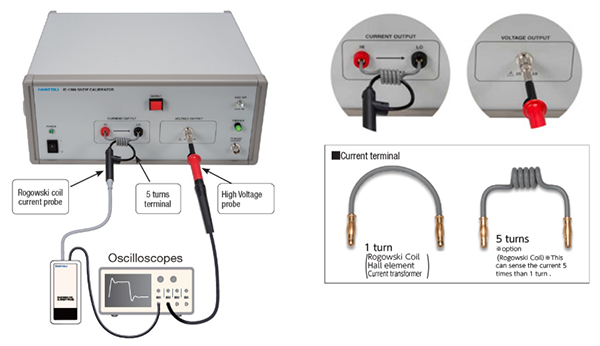
Probe calibrator
Skew calibrator (used to adjust the skew of voltage and current probes)
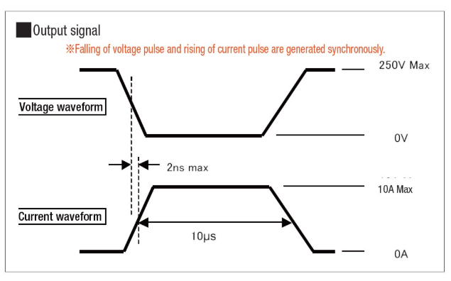
- This device can simultaneously generate a phase-matched voltage pulse and current pulse of up to 250V/10A, so it is ideal for skew (delay time) correction of high voltage probes and high current probes used for inverter measurement.
- Precise power measurement can be performed by accurately correcting the skew (delay time) of voltage probes and current probes.
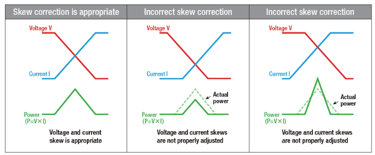
Reason for voltage waveform and current waveform skew (delay time) correction
If you do not correct the skew accurately, you will get different results from the real power loss waveform as shown in the figure below.
For high-precision power measurement, skew (delay time) correction of voltage and current probes is required.
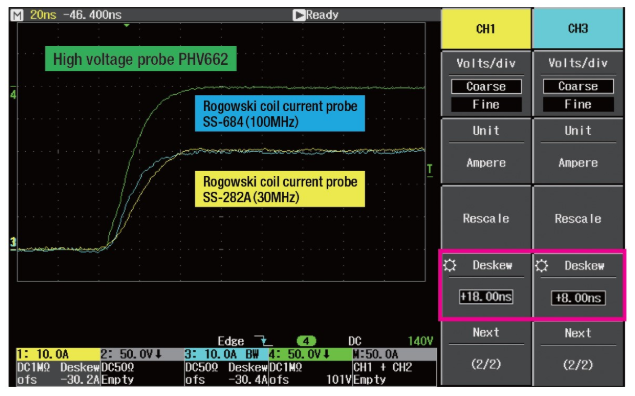
Application example
Specifications
| Item | Description | ||
|---|---|---|---|
| Output waveform | A single pulse with a pulse width of about 10μs | ||
| Generated signal range | 2 range switching | ||
| Voltage output | Voltage | 250V | 125V |
| Amplitude accuracy | ± 5% | ||
| output resistance | approx. 25Ω | ||
| Max load | 100kΩ or higher//12pF or lower | ||
| Output terminal | BNC connector (female) | ||
| Current output | Current | 10A | 5A |
| Amplitude accuracy | ± 5% | ||
| Output terminal | 1 turn (accessory)/5 turns (option) Replaceable | ||
| droop | 11%/μs or less | ||
| Waveform/Phase | Tr (current) | 25ns | 20ns |
| Tf (voltage) | |||
| Delay time difference | ± 2ns | ± 1.5ns | |
| Notes | *Guaranteed value only for the rising part of the current and the falling part of the voltage. *Pulse generation in the case of the standard terminal shape | ||
| trigger/output interval | 1 pulse occurrence/1 second or more by pressing the trigger button | ||
| Trigger output | Trigger output 0 to 4V (rising edge) | ||
| Power supply | 100VAC 20VA or less | ||
| Performance warranty temperature range | +10ºC ~ +35ºC | ||
| Dimensions (mm) | 320W × 160H × 270L (TBD) | ||