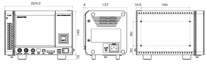
Modular Type Data Platform GL7000
*Please note that the Voltage Output Module (GL7-DCO), High Voltage Module (GL7-HV), and Logic/Pulse Module (GL7-L/P) have been discontinued.
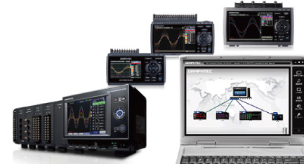
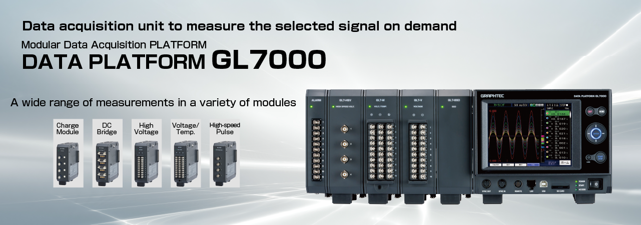
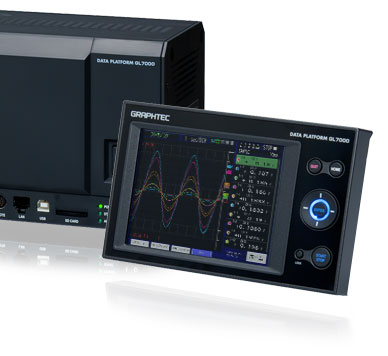
Modular Data Acquisition Platform GL7000
GL7000 can be used for a wide range of applications in various measurement scenarios by expanding the module. Removable touch panel display module allows both “stand-alone” and “system embedded” applications. Also, by attaching a display module, various settings and measurements can be done without a PC.
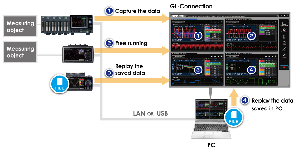
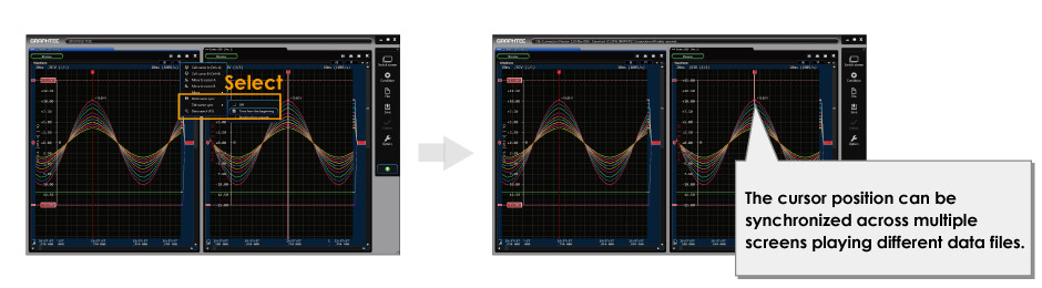
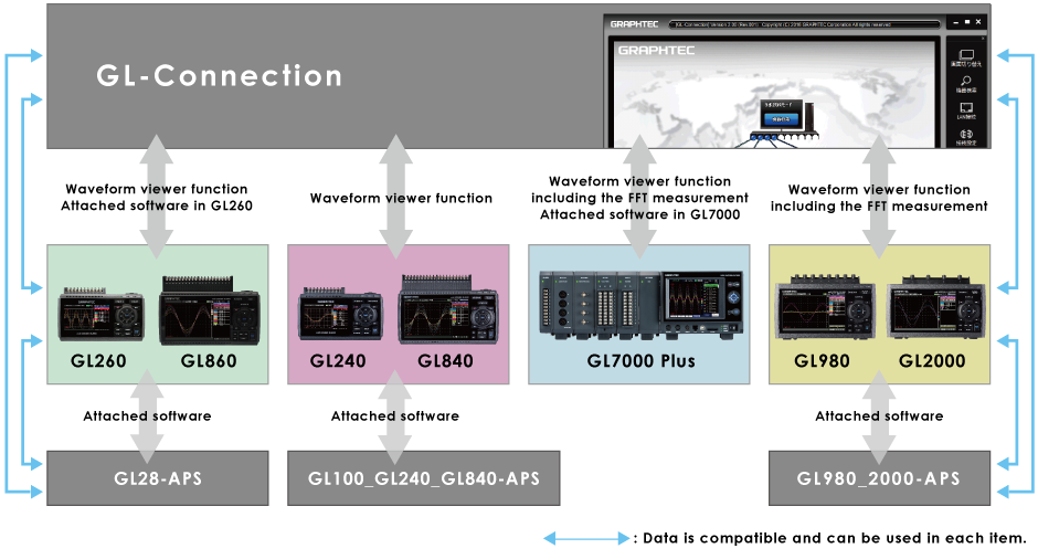
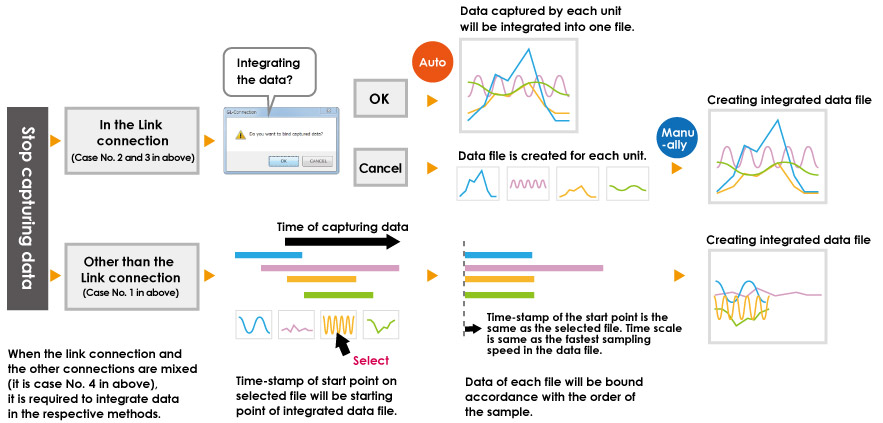
“GL-Connection”, the integrated waveform viewer for the GL series is included as a standard accessory.
It can manage various information such as “recording data” and “waveform data playback stored in the GL7000 main unit or PC”.
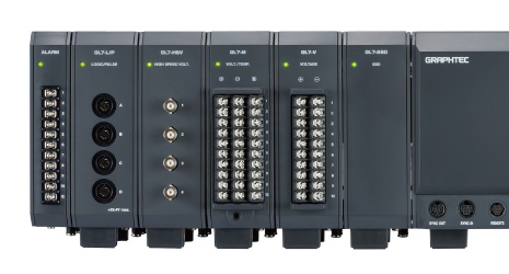
Modules Enable Wide Range of Measurements
Measurements for different applications can be added to the module. It is also possible to mix measurements by adding different types of modules.
| Voltage module(GL7-V) | Voltage/Temp. module(GL7-M) | High-speed voltage module(GL7-HSV) |
 |  |  |
| Bridge module(GL7-DCB) | Charge module(GL7-CHA) | |
 |  |
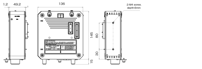
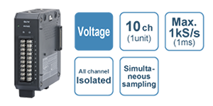
Voltage Module GL7-V (option) specification
| Item | Description | |||
|---|---|---|---|---|
| Model number | GL7-V | |||
| Number of input channels | 10 channels | |||
| Input method | All channels isolated unbalanced input, Simultaneous sampling, Screw terminal (M3 screw) | |||
| Sampling speed (interval) | 1 k Samples/s to 1 Sample/h (1 ms to 1 hr.) | |||
| Built in RAM | 2 million samples for each channel | |||
| Measurement range | 100, 200, 500 mV, 1, 2, 5, 10, 20, 50, 100 V, and 1-5 V Full Scale | |||
| Measurement accuracy (*1) | ±0.25% of Full Scale | |||
| A/D converter | Successive approximation type, 16 bits (effective resolution: 1/40000 of the measuring full range) | |||
| Input impedance | 1MΩ±5% | |||
| Maximum input voltage | Between (+)/(-) terminal | 100 mV to 1 V range: 60 Vp-p, 2 V to 100 V range: 100 Vp-p | ||
| Between channels ((-) terminals) | 60Vp-p | |||
| Between channel/GND | 60Vp-p | |||
| Max. voltage (withstand) | Between channels | 1000 Vp-p (1 minute) | ||
| Between channel/GND | 1000 Vp-p (1 minute) | |||
| Isolation | Between input/GND | Min. 50 MΩ (at 500 V DC) | ||
| Common-mode rejection ratio | Min. 90 dB (50/60 Hz, Signal source impedance: Max. 300 Ω) | |||
| Frequency response | DC~1kHz (+1/-3dB) | |||
| Filter | Low pass | Off, Line(1.5 Hz), 5, 50, 500 Hz (at -3 dB, 6dB/oct) | ||
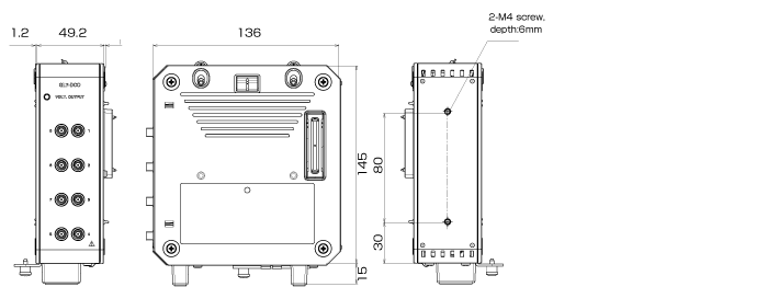
| External dimensions (W×D×H) | Approx. 49 x 136 x 160 mm (Excluding projections) | |||
| Weight | Approx. 840 g | |||
- Subject to the conditions:
● Room temperature is 23℃ ±5℃. ● When 30 minutes or more have elapsed after power was turned on.
● Filter is set to 10 or Line. ● Sampling rate is set to 1 second.
● GND terminal is connected to ground.
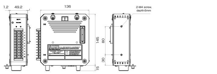
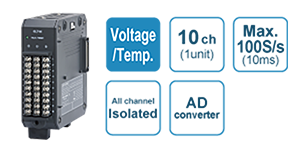
Voltage/Temperature Module GL7-M (option) specification
| Item | Description | ||||
| Model number | GL7-M | ||||
| Number of input channels | 10 channels | ||||
| Input method | All channels isolated balanced input, Scans channels for sampling, Screw terminal (M3 screw) | ||||
| Sampling speed (interval) | 100 Samples/s at 10ch to 1 Sample/h (10 ms at 10ch to 1 hr.) | ||||
| Built in RAM | 2 million samples for each channel | ||||
| Measurement range | Voltage | 20・50・100・200・500mV、1・2・5・10・20・50、1-5V F.S. | |||
| Temperature | Thermocouple: K, J, E, T, R, S, B, N, and W (WRe5-26) RTD: Pt100, JPt100 (JIS), Pt1000 (IEC751) | ||||
| Humidity | 0 to 100 % RH, using optional humidity sensor (B-530) | ||||
| Measurement accuracy (*1) | Voltage | ±0.1% of F.S. | |||
| Temperature | Thermocouple | Measurement range (TS: Temperature Sensed) | Measurement accuracy | ||
| R/S | 0≦TS≦100℃ | ±5.2℃ | |||
| 100<TS≦300℃ | ±3.0℃ | ||||
| R:300<TS≦1600℃ | ±(0.05% of rdg +2.0℃) | ||||
| S:300<TS≦1760℃ | ±(0.05% of rdg +2.0℃) | ||||
| B | 400≦TS≦600℃ | ±3.5℃ | |||
| 600<TS≦1820℃ | ±(0.05% of rdg +2.0℃) | ||||
| K | -200≦TS≦-100℃ | ±(0.05% of rdg +2.0℃) | |||
| -100<TS≦1370℃ | ±(0.05% of rdg +1.0℃) | ||||
| E | -200≦TS≦-100℃ | ±(0.05% of rdg +2.0℃) | |||
| -100<TS≦800℃ | ±(0.05% of rdg +1.0℃) | ||||
| T | -200≦TS≦-100℃ | ±(0.1% of rdg +1.5℃) | |||
| -100<TS≦400℃ | ±(0.1% of rdg +0.5℃) | ||||
| J | -200≦TS≦-100℃ | ±2.7℃ | |||
| -100<TS≦100℃ | ±1.7℃ | ||||
| 100<TS≦1100℃ | ±(0.05% of rdg +1.0℃) | ||||
| N | -200≦TS<0℃ 0≦TS≦1300℃ | ±(0.1% of rdg +2.0℃) ±(0.1% of rdg +1.0℃) | |||
| C (Prev. W: WRe5-26) | 0≦TS≦2000℃ | ±(0.1% of rdg +1.5℃) | |||
| Reference Junction Compensation (R.J.C.) accuracy: ±0.5℃ * Wire size of thermocouple used is 0.32 mm diameter in the T type and 0.65 mm diameter in other types. | |||||
| RTD | Measurement range | Driving current | Accuracy | ||
| Pt100 | -200~850℃(FS=1050℃) | 1mA | ±1.0℃ | ||
| JPt100 | -200~500℃(FS=700℃) | 1mA | ±0.8℃ | ||
| Pt1000 | -200~500℃(FS=700℃) | 0.2mA | ±0.8℃ | ||
| R.J. Compensation | Select internal or external | ||||
| A/D converter | Sigma-Delta type, 16 bits (effective resolution: 1/40000 of the measuring full range) | ||||
| Input impedance | 1 MΩ ±5% | ||||
| Maximum input voltage | Between (+)/(-) terminal | 60Vp-p | |||
| Between channels ((-) terminals) | 60Vp-p | ||||
| Between channel/GND | 60Vp-p | ||||
| Max. voltage (withstand) | Between channels | 350 Vp-p (1 minute) | |||
| Between channel/GND | 350 Vp-p (1 minute) | ||||
| Isolation | Between input/GND | Min. 50 MΩ (at 500 V DC) | |||
| Common-mode rejection ratio | Min. 90 dB (50/60 Hz, Signal source impedance: Max. 300 Ω) | ||||
| Filter | Off, 2, 5, 10, 20, 40 (Moving average in selected number. When the sample is longer than 5 seconds, the data sampled in the sub-sample (5 seconds) will be used for creating the average value.) | ||||
| 5 V output | Driving the humidity sensor B-530, 1 channel | ||||
| External dimensions (W×D×H) | Approx. 49 x 136 x 160 mm (Excluding projections) | ||||
| Weight | Approx. 770 g | ||||
- Subject to the conditions:
● Room temperature is 23℃ ±5℃. ● When 30 minutes or more have elapsed after power was turned on.
● Filter is set to 10 or Line. ● Sampling rate is set to 1 second.
● GND terminal is connected to ground.
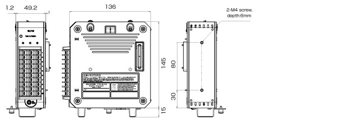
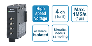
High-speed Voltage Module GL7-HSV (option) specification
| Item | Description | |
| Model number | GL7-HSV | |
| Number of input channels | 4 channels | |
| Input method | All channels isolated unbalanced input, Simultaneous sampling, BNC connector | |
| Sampling speed (interval) | 1 M Samples/s to 1 Sample/h (1μs to 1 hr.) | |
| Built in RAM | 2 million samples for each channel | |
| Measurement range | 100, 200, 500 m , 1, 2, 5, 10, 20, 50, 100 V, and 1-5 V Full Scale | |
| Measurement accuracy (*1) | ±0.25% of Full Scale | |
| A/D converter | Successive approximation type, 16 bits (effective resolution: 1/40000 of the measuring full range) | |
| Maximum input voltage | Between (+)/(-) terminal | 100 m to 1 V range: 60 VP-p, 2 V to 100 V range: 100 VP-p |
| Between channels ((-) terminals) | 60Vp-p | |
| Between channel/GND | 60Vp-p | |
| Max. voltage (withstand) | Between channels | 1000 VP-p (1 minute) |
| Between channel/GND | 1000 VP-p (1 minute) | |
| Isolation | Between input/GND | Min. 50 M (at 500 V DC) |
| Common-mode rejection ratio | Min. 90 dB (50/60 Hz, Signal source impedance: Max. 300 Ω) | |
| Frequency response | DC to 200 kHz (+1/-3 dB) | |
| Filter | Low pass | Off, Line(1.5 Hz), 5, 50, 500, 5k, 50k Hz (at -3 dB, 6dB/cot) |
| External dimensions (W×D×H) | Approx. 49 x 136 x 160 mm (Excluding projections) | |
| Weight | Approx. 740 g | |
- Subject to the conditions:
● Room temperature is 23℃ ±5℃. ● When 30 minutes or more have elapsed after power was turned on.
● Filter is set to 10 or Line. ● Sampling rate is set to 1 second.
● GND terminal is connected to ground.
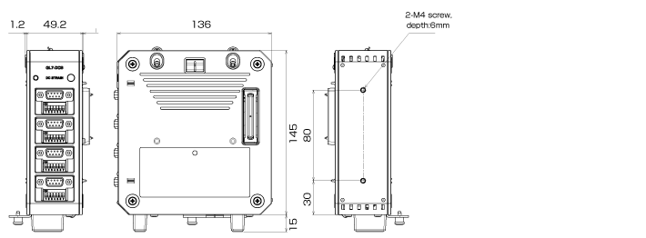
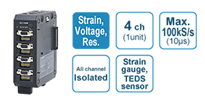
DC Strain Module GL7-DCB (option) specification
| Item | Description | |
| Model number | GL7-DCB | |
| Number of input channels | 4 channels | |
| Input method | All channels isolated balanced input, Simultaneous sampling, D-SUB type connector (9 pins, receptacle) | |
| Sampling speed (interval) | 100 k Samples/s to 1 Sample/h (10 μs to 1 hr.) | |
| Built in RAM | 2 million samples for each channel | |
| Input type | Strain, Voltage, Resistance value (including potentiometer) | |
| Measurement range | Strain | 500, 1000, 2000, 5000, 10000, 20000 με (με: 10-6 strain) 0.2, 0.25, 0.4, 0.5, 1, 2, 2.5, 4, 5, 10 mV/V * Available ranges vary by the excitation voltage for the bridge. |
| Voltage | 1, 2, 5, 10, 20, 50, 100, 200, 500 mV, 1, 2, 5 V Full Scale | |
| Resistance | 1, 2, 5, 10, 20, 50, 100, 200, 500 Ω, 1, 2, 5, 10, 20, 50 kΩ Full Scale | |
| Measurement accuracy (*1) | Strain | ±(0.2% of F.S. +10με) |
| Voltage | ±(0.2% of F.S. +10μV) | |
| Resistance | ±0.5% of Full Scale (More than 1 hour elapsed after power-on) | |
| A/D converter | Successive Approximation type, 16 bits (effective resolution: 1/40000 of the measuring full range) | |
| Gauge ratio | 2.0 constant | |
| Supported sensor | Strain (*2) | Strain gauge Quarter bridge (single gauge) in 2-, 3- or 4-wire (supports remote sensing in 3- or 4-wire) Half bridge (dual gauge) in 3-, 4-, 5-wire (supports remote sensing in 4- or 5-wire) Full bridge (quad gauge) in 4- or 6-wire (supports remote sensing in 6-wire) |
| Transducer/sensor based on a strain gauge Full bridge type in 4-wire, Full bridge type in 6-wire (supports remote sensing) | ||
| Resistance | Resistor, Potentiometer | |
| Bridge resistance | 50 Ω to 10 kΩ * Available excitation power varies by selection of element. | |
| Built-in element of the bridge8 | 120 or 350 Ω for the quarter- and half-bridge * Available excitation power varies by selection of element. | |
| Excitation power | Voltage mode | 1, 2, 2.5, 5, 10 V DC * Excitation voltage 5 and 10 V is available when bridge resistance is the 350 Ω or higher. |
| Excitation power | Voltage mode | 1, 2, 2.5, 5, 10 V DC * Excitation voltage 5 and 10 V is available when bridge resistance is the 350 Ω or higher. |
| Current mode | Constant current: 0.1 to 20 mA (supported voltage is up to 10 V.) | |
| Zero Adjust for Strain gauge | Method | Fully automatic (via push button or setting the condition menu) |
| Max. Range | ±10,000με (με:10-6 Strain) | |
| Remote sensing | 3- or 4-wire in quarter bridge, 4- or 5-wire in half bridge, 6-wire full bridge | |
| Shunt Calibration | Approx. 60 kΩ (120 Ω gauge), Approx. 175 kΩ (350 Ω gauge) | |
| Input impedance | 10MΩ±5% | |
| Maximum input voltage | Between (+) / (-) terminal | 10 V, Common-mode voltage: 10 Vrms AC |
| Between channels ((-) terminals) | 10Vp-p | |
| Between channel / GND | 60Vp-p | |
| Max. voltage (withstand) | Between channel / GND | 1000 Vp-p (1 minute) |
| Isolation | Between channel / GND | Min. 100 MΩ (at 500 V DC) |
| Common-mode rejection ratio | Min. 80 dB (50/60 Hz, Signal source impedance: Max. 300 Ω) | |
| Frequency response | DC~20kHz | |
| Filter | Low pass | Off, Line (1.5 Hz), 3, 6, 10, 30, 50, 60, 100, 300, 500 Hz, 1k, 3k, 5k, 10k Hz (in -30dB/oct) |
| Anti-aliasing | Off, On | |
| Support TEDS | Standard | IEEE 1451.4 Class2 (Temperate No.33) |
| Support | Reading information from the sensor and setting it to module | |
| External dimensions (W x D x H) | Approx. 49 x 136 x 160mm (Excluding Protection) | |
| Weight | Approx. 840 g | |
- Subject to the conditions:
● Room temperature is 23℃ ±5℃. ● When 30 minutes or more have elapsed after power was turned on.
● Filter is set to 10 or Line. ● GND terminal is connected to ground. - ● Remote sensing is not available when a NDIS connector is used. ● When a bridge box is used, the connection needs to be 4-wire or 6-wire full bridge. When connecting with a Half bridge (Opposite side), an additional bridge box is required. ● Bridge excitation: Constant current drives a strain gauge type sensor or a 4-wire full bridge. ● The shunt calibration is available only when the connection is using a 3-wire, 4-wire quarter bridge, 5-wire full bridge, or 6-wire full bridge.
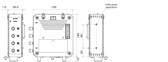
Charge Module GL7-CHA (option) specification
| Item | Description | |
| Model number | GL7-CHA | |
| Number of input channels | 4 channels | |
| Input method | All channels isolated unbalanced input, Simultaneous sampling, BNC and Miniature connector (#10-32UNF) | |
| Sampling speed (interval) | 10μs (100kS/s)~1h | |
| Built in RAM | 2 million samples for each channel | |
| Input coupling | Sensor: Charge-RMS, IEPE-RMS Voltage: DC, AC, DC-RMS, AC-RMS | |
| Measurement range | Acceleration sensor input | 1・2・5・10・20・50・100・200・500・1000・2000・5000・10000・20000・50000m/s2 |
| Voltage input | AC、DC:50・100・200・500mV、1・2・5・10V RMS :20・50・100・200・500mVrms、1・2・5Vrms クレストファクタ:(~2Vrmsレンジ)4以下、(5Vrmsレンジ)2以下 | |
| Microphone input (*1) | 200・400・500mPa・1・2・4・5・10・20・40・50・100・200・400・500Pa | |
| Supported sensor sensitivity | Charge output type | 0.01 pC/(m/s2) to 999.9 pC/(m/s2) Effective range of measurement range varies depending on sensor sensitivity. |
| IEPE type | 0.01 mV/(m/s2) to 999.9 mV/(m/s2) Effective range of measurement range varies depending on sensor sensitivity. | |
| Microphone (*1) | 0.2 mV/Pa to 100 mV/Pa | |
| Measurement accuracy (*2) | Charge output type | ±0.9% of Full Scale ([sensor sensitivity] × [setting range] ≥ 20 pC) |
| In RMS (by Sine wave): ±1.4% of Full Scale at 20 Hz to 1 kHz | ||
| IEPE type | ±0.25% of Full Scale ([sensor sensitivity] × [setting range] ≥ 200 mV) | |
| In RMS (by Sine wave): ±0.75% of Full Scale at 20 Hz to 1 kHz | ||
| Microphone | ±0.25% of Full Scale ([sensor sensitivity] × [setting range] ≥ 200 mV) | |
| Voltage | ±0.25% of Full Scale | |
| In DC-RMS (by Sine wave): ±0.5% of Full Scale at 20 Hz to 1 kHz ±1.5% of Full Scale at 1 kHz to 5 kHz | ||
| In AC-RMS (by Sine wave): ±0.5% of Full Scale at 100 Hz to 1 kHz ±1.5% of Full Scale at 1 kHz to 5 kHz | ||
| A/D converter | Successive Approximation type, 16bits (effective resolution: 1/40000 of the measuring full range) | |
| Input impedance | 100kΩ±5% | |
| Excitation power | 4 or 8 mA (supported voltage: 22 V ±10%) | |
| Maximum input charge signal | Max. 50000 pC | |
| Maximum input voltage | Between (+) / (-) terminal | 25Vp-p |
| Between channels ((-) terminals) | 25Vp-p | |
| Between channel / GND | 25Vp-p | |
| Max. voltage (withstand) | Between channels | 300 Vp-p (1 minute) |
| Between channel / GND | 300 Vp-p (1 minute) | |
| Isolation | Between input / GND | 300 Vp-p (1 minute) |
| Common-mode rejection ratio | Min. 80 dB (50/60 Hz, Signal source impedance: Max. 300 Ω) | |
| Frequency response | Charge type | 1.5Hz~45kHz |
| IEPE type | 1Hz~45kHz | |
| Filter | Hi pass | Off, 0.15, 1, 10 Hz (It depends on input conditions.) |
| Low pass | Off, Line(1.5 Hz), 3, 6, 10, 30, 50, 60, 100, 300, 500 Hz, 1k, 3k, 5k, 10k Hz (in -30dB/oct) | |
| Anti-aliasing | Off, On | |
| Support TEDS | Standard | Acceleration sensor: IEEE 1451.4 Class1 (Temperate No.25) Microphone: IEEE 1451.4 Class1 (Temperate No.27) |
| Support | Reading information from the sensor and setting it to module | |
| Calculation function | Integration (convert measurement to velocity), Double Integration (convert measurement to displacement) | |
| External dimensions (W x D x H) | Approx. 49 x 136 x 160mm (Excluding projections) | |
| Weight | Approx. 850 g | |
- It is required firmware version 2.0 or later.
- Subject to the conditions:
● Room temperature is 23℃ ±5℃. ● When 30 minutes or more have elapsed after power was turned on.
● Filter is set to 10 or Line. ● GND terminal is connected to ground.
Measurement accuracy of RMS is effective for input voltage of 5 to 100% in each measurement range.
Discontinued unit
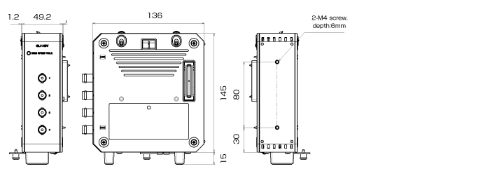
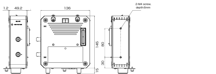
High Voltage Module GL7-HV (option) specification Discontinued
| Item | Description | |
| Model number | GL7-HV | |
| Number of input channels | 2 channels | |
| Input method | All channels isolated unbalanced input, Simultaneous sampling, Isolated BNC connector | |
| Sampling speed (interval) | 1μs (1MS/s)~1h | |
| Built in RAM | 2 million samples for each channel | |
| Input coupling and measurement | AC, DC, AC-RMS, DC-RMS | |
| Measurement range | DC、AC | 2, 5, 10, 20, 50, 100, 200, 500, 1000 V Full Scale |
| DC-RMS、AC-RMS | 1・2・5・10・20・50・100・200・500Vrms F.S. ク1, 2, 5, 10, 20, 50, 100, 200, 500 Vrms Full Scale (Crest Factor: up to 4 in 1 to 200 Vrms range, up to 2 in 500 Vrms range) | |
| Measurement accuracy (*1) | DC、AC | ±0.25% of Full Scale |
| DC-RMS | Sine wave measurement ±0.5% of Full Scale (at 20 Hz ≤ F ≤ 1 kHz) ±1.5% of Full Scale (at 1 kHz < F ≤ 20 kHz) Response time: 500ms (Crest Factor is up to 4) | |
| AC-RMS | Sine wave measurement ±0.5% of Full Scale (at 100 Hz ≤ F ≤ 1 kHz) ±1.5% of Full Scale (at 1 kHz < F ≤ 20 kHz) Response time: 500 ms (Crest Factor is up to 4) | |
| A/D converter | Successive Approximation type, 16 bits (effective resolution: 1/40000 of the measuring full range in the DC and AC coupling, 1/20000 of the measuring full range in the DC-RMS, AC-RMS coupling) | |
| Input impedance | 1MΩ±5% | |
| Maximum input voltage | Between (+)/(-) terminal | 1000Vp-p |
| Between channels ((-) terminals) | 300 Vrms AC | |
| Between channel/GND | 300 Vrms AC | |
| Max. voltage (withstand) | Between channels | 2300 Vrms AC (1 minute) |
| Between channel/GND | 2300 Vrms AC (1 minute) | |
| Isolation | Between input/GND | Min. 50 MΩ (at 500 V DC) |
| Common-mode rejection ratio | Min. 90 dB (50/60 Hz, Signal source impedance: Max. 300 Ω) | |
| Frequency response | DC Coupling: DC to 200 kHz (+1/-3 dB) AC Coupling: 4Hz to 200 kHz (+1/-4.5 dB) | |
| Filter | Low pass | OFF, Line (1.5 Hz), 5, 50, 500, 5k, 50k Hz (at -3 dB, 6dB/oct) |
| External dimensions (W×D×H) | Approx. 49 x 136 x 160mm (Excluding projections) | |
| Weight | Approx. 740 g | |
- Subject to the conditions:
● Room temperature is 23℃ ±5℃. ● When 30 minutes or more have elapsed after power was turned on.
● Filter is set to 10 or Line. ● GND terminal is connected to ground.
Measurement accuracy of RMS is effective for input voltage of 5 to 100% in each measurement range.
Analog voltage output module GL7-DCO (option) specification Discontinued
| Item | Description | |
| Model number | GL7-DCO | |
| Number of input channels | 8 channels | |
| Output connector | SMA (Sub-miniature version A) connector | |
| Output method | All channels common ground, SMA (Sub-miniature version A) connector | |
| Sampling speed (interval) | Up to 100 k Samples/s (10 μs) | |
| Output condition | Source of data | Measurement data, Edited measurement data, Generated arbitrary data (*1), Generated simple waveform (DC voltage and sine, triangle, ramp, pulse waveform) |
| Source of measurement data | Module of Voltage (GL7-V), Voltage/Temperature (GL7-M), High speed voltage (GL7-HSV), High voltage (GL7-HV), DC strain (GL7-DCB), and Charge (GL7-CHA) | |
| Output condition | Signal can be measured by the input module even while the signal is output from the DCO module. Measurement data except the temperature, humidity and logic/pulse are able to output. | |
| Output range | ± 1, 2, 5, 10 V Full Scale | |
| Output signal accuracy (*2) | ±0.25% of Full Scale | |
| D/A converter | Resolution 16 bits (effective resolution: 1/20000 of the output full range) | |
| Filter | Low pass | OFF, Line(1.5 Hz), 5, 50, 500, 5k, 50k Hz * This filter is the smoothing filter to remove the noise on output of the D/A converter. |
| External dimensions (W x D x H) | Approx. 49 x 136 x 160mm (Excluding projections) | |
| Weight | Approx. 770g | |
- It is required to create the CSV file that is the source for the arbitrary data using the GL-Wave Editor (EXCEL macro). The Microsoft EXCEL 2003 (Office 2003) or later edition is required to use the GL-Wave Editor.
- Subject to the conditions: ● Room temperature is 23oC ±5oC. ● When 30 minutes or more have elapsed after power was turned on.
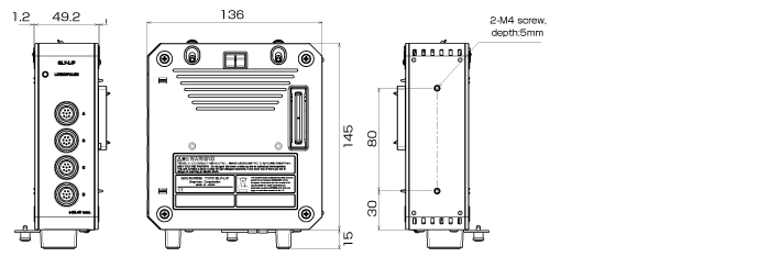
Logic / Pulse Module GL7-L/P (option) specification Discontinued
| Item | Description | |
| Model number | GL7-L/P | |
| Number of input channels | 16 channels | |
| Input method | All channels common ground, Simultaneous sampling, Circular connector (4ch/connector) (*1) | |
| Sampling speed (interval) | Logic mode | 1 M Samples/s to 1 Sample/h (1 μs to 1 hr.) |
| Pulse mode | 10 k Samples/s to 1 Sample/h (100 μs to 1 hr.) | |
| Built in RAM | 2 million samples for each channels | |
| Measurement mode | Logic input mode or Pulse input mode (*2) | |
| Pulse input mode | Rotation count (RPM), Accumulating count, Instant count | |
| Rotation count (RPM) | Function | Counting the number of pulses per sampling interval and then it is converted to RPM |
| Span | 50, 500, 5000, 50 k, 500 k, 5 M, 50 M, 500 M rpm Full Scale | |
| Accumulating count | Function | Accumulating the number of pulses from the start of measurement |
| Span | 50, 500, 5000, 50 k, 500 k, 5 M, 50 M, 500 M counts Full Scale | |
| Instant count | Function | Counting the number of pulses per sampling interval (count is reset at each sampling) |
| Span | 50, 500, 5000, 50 k, 500 k, 5 M, 50 M, 500 M counts Full Scale | |
| Maximum input frequency | 1MHz | |
| Maximum number of count | 15 M counts (24 bits counter is used) | |
| Input signal | Voltage range | 0 to 24 V (common ground) |
| Signal type | Contact (Relay), Open collector, Voltage | |
| Threshold | Approx. 2.5 V | |
| Hysteresis | Approx. 0.5 V (2.5 V to 3 V) | |
| Filter | Off or On (-3 dB at 50 Hz) | |
| External dimensions (W×D×H) | Approx. 49 x 136 x 160 mm (Excluding projections) | |
| Weight | Approx. 700 g | |
- Input prove (RIC-10A) is required to connect signals.
- The measuring mode is set in each module (16 channels). In Logic mode, up to 7 modules (Up to 112ch.) can be attached to one main module. In Pulse mode, up to 2 modules (Up to 32ch.) can be attached to one main modules. The maximum number of module and channels are limited to up to 10 units with a mixed condition and 112 channels.
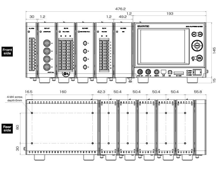
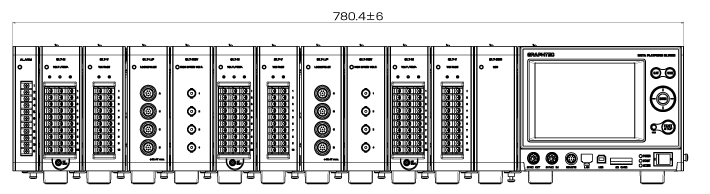
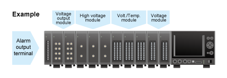
Up to 10 input/output modules can be attached to one main unit
Input module can be expanded to accommodate a wide variety of measurement.
Each of the 10 units can include a different input/output module (*1)
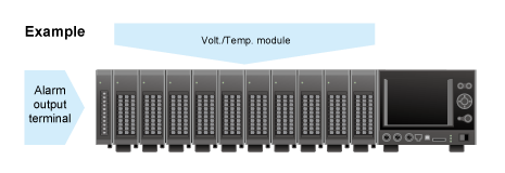
Up to 10 input/output modules of the same kind can be attached to one main unit (*1)
- * If different types of modules are attached, the effective sampling speed of the system is to up to the fastest sampling speed among the installed modules. When the maximum sampling speed of the module is slower than the maximum sampling speed of the fastest amplifier, signal will be sampled with maximum sampling speed of the module. The same data is saved with the system sampling speed until new data is captured on the slower units.
* The number of modules that can be attached is limited by the type of module. Up to 10 modules (maximum 112ch with 7 GL7-L/P module, max 100ch with GL7-V or GL7-M module).
For Logic/Pulse module (GL7-L/P):
Maximum 7 units allowed using logic option (112ch).
Maximum 2 units allowed using pulse option (32ch).
(The mode for logic or pulse can be set for each unit.)
For Strain module (GL7-DCB):
Maximum 8 units allowed with additional two other amplifier units. (Number of channels is limited to 112ch.)
* For the logic/pulse module, the number of channels can be limited by the selected sampling speed when the module is attached together with other amplifier modules.
1μs sampling interval: up to 8 channels
2μs sampling interval: up to 16 channels (If two modules are attached, channel #1 to #8 in each unit can be used.)
When pulse mode is used, the maximum sampling speed is the 100μs. The data will be updated every 100μs.
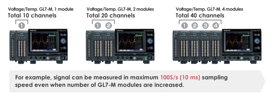
Same Max. Sampling Speed Regardless of the Number of Input / Output Mo
Same Max. Sampling Speed Regardless of the Number of Input / Output Modules
Maintains the maximum sampling speed even when the number of input modules for voltage or voltage/temperature are increased.
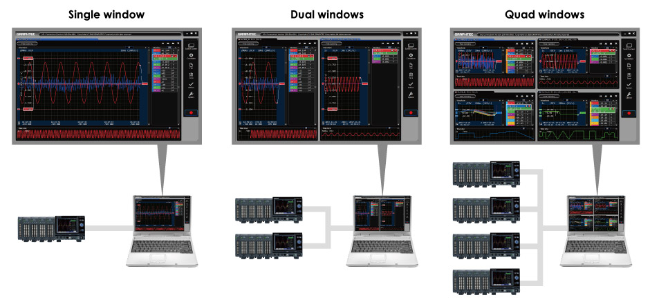
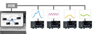
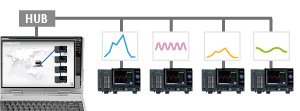
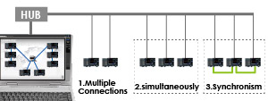
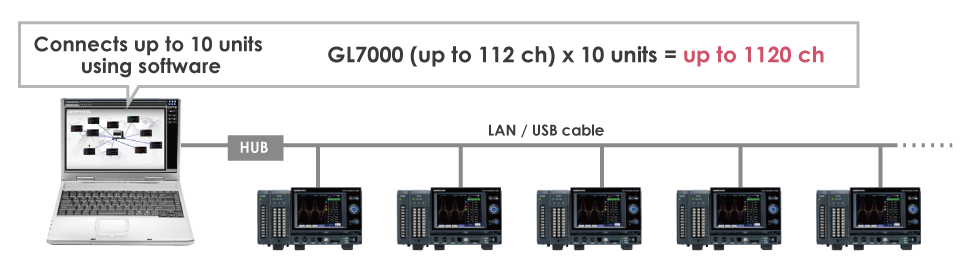
Up to 1120 channels can be measuring using the PC platform
Up to 10 units of the GL7000 can be connected to 1PC through LAN or USB and controlled using the software.
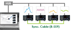
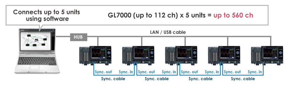
Max. 5 Units of GL7000 Can be Fully Synchronized Using the Sync. Cable
The start/stop, trigger and sampling can be synchronized in the GL7000 when they are connected by a sync. cable (option “B-559”). The master and slave units are automatically identified.
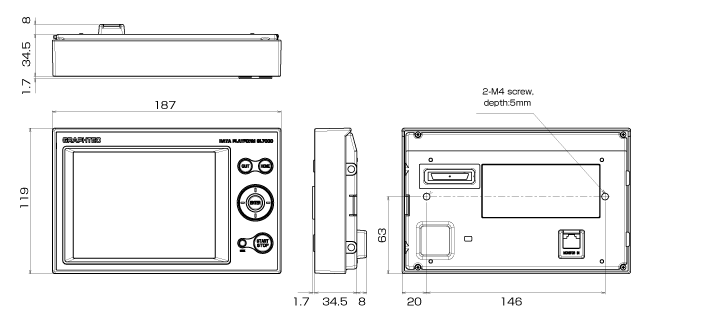
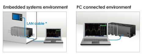
High-definition Display Module with Touch Panel Enables Measurement in Various Configuration
The detachable display module allows both stand-alone and embedded system configurations
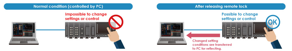
Measurement settings and signal measurement can both be done without a PC by attaching the display module. The display module can be moved to different locations for remote operation by connecting it to the main module with a LAN cable*, it also can be embedded into the system. The module can stile be operated by the PC even when the display module is connected.
*Up to 10m using CAT5 LAN cable (straight connection)
Large easy-to-read 5.7-inch (VGA 640 x 480) high-definition LCD monitor
Utilizes a bright clear TFT color LCD monitor.
Makes it easy to read data in waveform or digital form and to check measurement parameter settings.
Supports Multiple Destinations to Save the Captured Data According to the Conditions of the Measurement
Supports multiple types of storage
- Built-in RAM
- Built-in Flash memory
- SD memory card
- SSD module (128GB)
Useful functions for reacording and replaying data
- Dual-Sampling Feature
- Enhanced relay recording function
- Ring mode
- Back up recording data
Useful tools (optional)
- Carrying tool (B-585)
- Storage case (B-586)
- Input connector, screw terminal (B-560A)
- Extension cable for B-560/B-560A connector