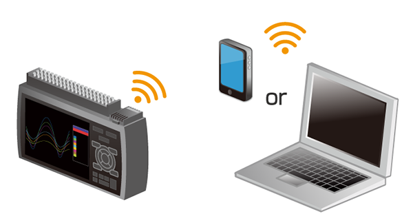
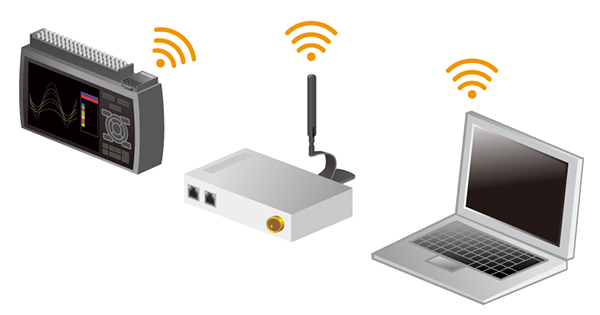
Wireless measurement from your PC is available with the optional wireless LAN unit.
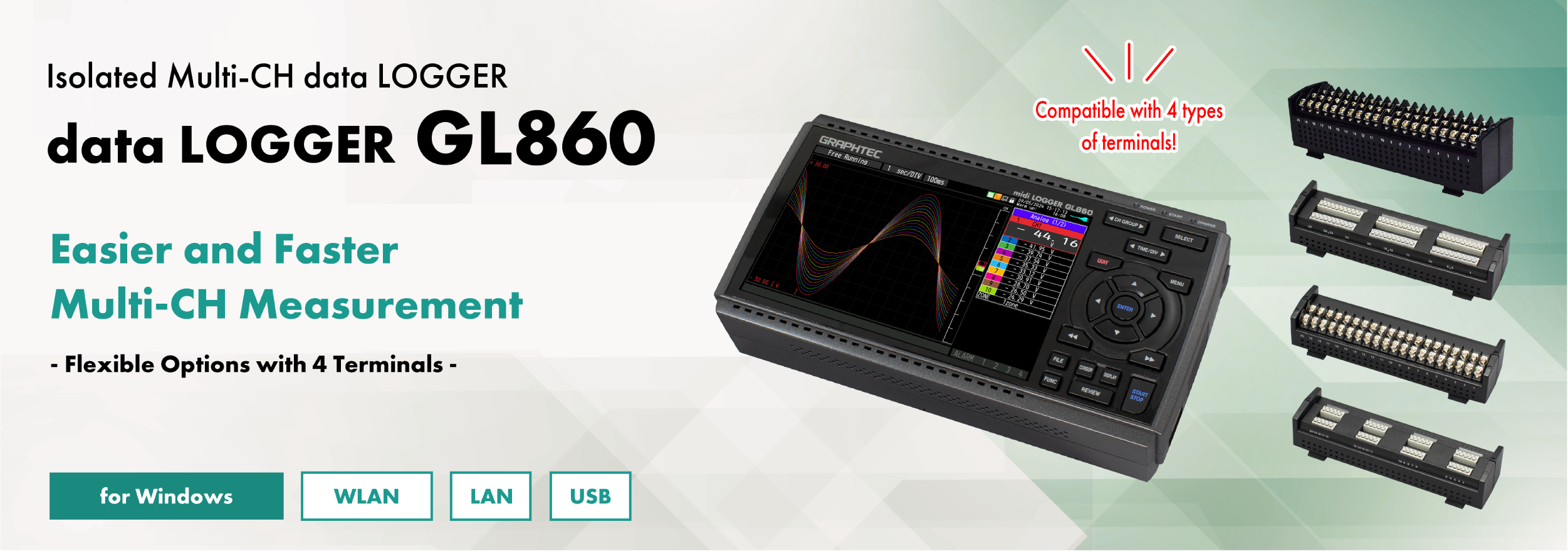
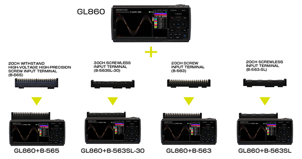
All Channel Isolated / Universal Input, Standalone Multi-Channel
Voltage, temperature, and humidity can be selected for each input channel. Use EU scaling for other measurement parameters.
Measure voltage
Supports wide operating range (from 20 mV to 100 V)
Measure temperature
Thermocouple: K, J, E, T, R, S, B, N, C(old W:WRe5-26) RTD*: Pt100・JPt100・Pt1000(IEC751) (only 3 wire type is supported) *Please use B-565 for connecting the RTD
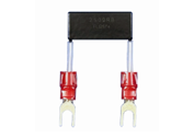
Measure current (4 -20 mA)
Shunt resistor (250Ω) is available as an option. Equipped with a dedicated 1-5V range for the measurement range
Shunt resistance 250Ω (B-551)
*Cannot be used with the screwless terminal
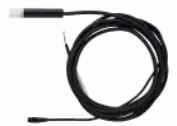
Measure humidity
A humidity sensor is available as an option. Power for the sensor is also supplied from the main unit. Equipped with a dedicated humidity range
Humidity sensor (B-530)
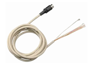
Digital I/O port available
Digital I / O can be used by connecting an optional I / O cable.
Input/Output cable (B-513)
<Logic/Pulse inputs (4 channels)>
Logic : No-voltage contact (A contact, B contact, NO, NC) ,Open collector, Voltage input (H.L decision) Pulse : 3 types of selections (Rotation / Quantity count / Instantaneous) per channel
<Alarm output: 4ch>
Alarm conditions can be set for each input channel.
Signal output from outputs 1 to 4 is possible in the event of an alarm.
Photo MOS relay scanning system All channels isolated, balanced input
Measurement ranges※1
Voltage
20・50・100・200・500mV・1・2・5・10・20・50・100V、1-5V F.S.
Temperature
Thermocouples:K, J, E, T, R, S, B, N, C (W: WRe5-26)
RTD (only 3 wire type is supported) : Pt100, JPt100, Pt1000(IEC751)
(* RTD cannot be connected.)
Temperature range: 100°C, 500°C, 2000°C (In the case of Fahrenheit: 150°F, 750°F, 3000°F)
Humidity
0 to 100% (Optional humidity sensor B-530 is required)
Maximum permissible input voltage
Between +/– terminals
20mV to 2V range (60Vp-p) 5V to 100V range (110Vp-p)
Between input terminal/input terminal
600Vp-p
60Vp-p
Between input terminal/GND
300Vp-p
60Vp-p
Withstand voltage
Between input terminal/input terminal
600Vp-p
350Vp-p 1 minute
Between input terminal/GND
2300VACrms 1 minute
350Vp-p 1 minute
Voltage measurement accuracy
± (0.05% of F.S. +10μV)
±0.1% of F.S.
Operating environment
0~45℃
Dimensions(*including GL860)
240×166×52.5mm (exclude protrusion)
240×158×52.5mm (exclude protrusion)
Weight(*including GL860)
1035g (exclude AC adapter & battery)
1010g(exclude AC adapter & battery)
*Please refer to the user manual for the measurement accuracy of each terminal.
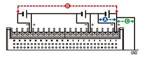
Maximum input voltage
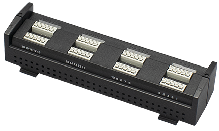
B-565 < Between +/– terminals (A) > – Maximum input voltage: 60Vp-p (Range of 20mV to 2V) 110Vp-p (Range of 5V to 100V) < Between input terminal/input terminal (B) > – Maximum input voltage: 600Vp-p – Withstand voltage: 600Vp-p < Between input terminal/GND (C) > – Maximum input voltage: 300Vp-p – Withstand voltage: 2300Vp-p at 1 minute
B-563SL-30 / B-563 / B-563SL < Between +/– terminals (A) > – Maximum input voltage: 60Vp-p (Range of 20mV to 2V) 110Vp-p (Range of 5V to 100V) < Between input terminal/input terminal (B) > – Maximum input voltage: 60Vp-p – Withstand voltage: 350Vp-p at 1 minute < Between input terminal/GND (C) > – Maximum input voltage: 60Vp-p – Withstand voltage: 350Vp-p at 1 minute
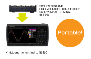
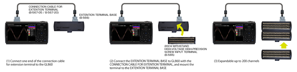
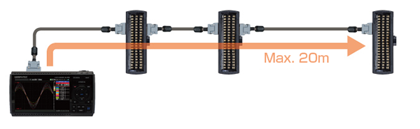
Channel Expansion of Analog Signal Input Port
Expandable up to 200 channels.
Example
20ch / 30ch
0ch or more (up to 200ch)
Example of channel expansion
スクロールできます
Number of channels
20ch
40ch
60ch
100ch
200ch
GL860
1
1
1
1
1
Connection cable for extension terminal (B-567-05/B-567-20)
–
1
1
1
1
Base unit for input terminal(B-566)
–
2
3
5
10
20ch terminal*1 (B-565/B-563/B-563SL)
1
2
3
5
10
*1. When using B-565 with other terminals, Withstand voltage: lower withstand voltage will be applied Accuracy: depends on the terminal
The input terminal and GL860 can be extended by using the connection cable for extension terminal (50cm / 2m)
*If the measurement is affected by noise, slow down the sampling interval.
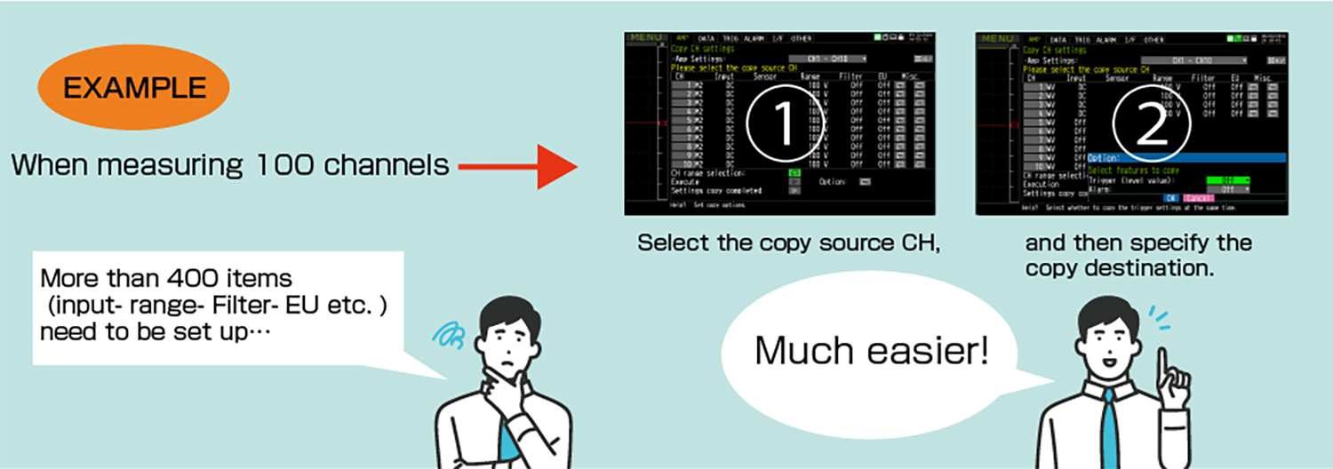
CH copy function is useful for multi-channel measurements
Copy settings such as input, range, filter, EU, etc. at once. The setup can be done simply by selecting a channel, greatly reducing the man-hours required. Trigger and alarm settings can also be copied
Maximum Sampling Interval of Up to 5ms
Up to 5ms sampling speed is achievable when limiting the number of channels in use.
スクロールできます
Sampling Interval
5ms
10ms
20ms
50ms
100ms
250ms
500ms
1s
Sampling Interval
1
2
4
10
20
50
100
200
Measuring
Voltage / Humidity
●
●
●
●
●
●
●
●
Temperature
–
–
–
–
●
●
●
●
Built-in 8GB Flash Memory with SD Card Support
Example of recording time (data size: 2GB)
スクロールできます
Sampling Interval
5ms
10ms
50ms
100ms
200ms
500ms
1s
10s
GBD format
15 days
24 days
47 days
54 days
108 days
270 days
366+ days
366+ days
CSV format
1 day
3 days
8 days
11 days
22 days
55 days
111 days
366+ days
*Figures are approximate. File size of captured data is 2GB in GBD or CSV file format on this chart. 5ms: 1ch, 10ms: 2ch, 20ms: 4ch, 50ms: 10ch
Ring capture function
The most recent data is saved when the memory is configured in ring memory mode. (Number of capturing data is 1000 to 2000000 points)
Relay capture function
Data is continuously saved to multiple files up to 2GB without losing any data until capturing is stopped when the memory is configured in the relay mode.
Memory loop function
In addition to the existing relay capture function, the oldest file is automatically deleted before memory capacity runs out.
Hot-swapping the SD memory card
SD card can be replaced during data capturing when the sampling interval is 100ms or slower. *When the wireless LAN is installed, the SD memory card cannot be inserted into the SD CARD slot.
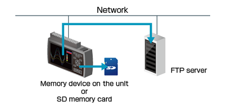
Back up recording data
The data file can be created periodically for purpose of backing up data while recording it, and the file is automatically transferred to another storage device on the unit or FTP server on the network.
Backup interval: 1, 2, 6, 12, 24 hour(s) Backup file destination: SD memory card or FTP server Data file format: GBD (binary) or CSV (text)
• The CSV format is available with firmware version 1.43 or rater. • Available sampling speed is the 100 ms or slower when using the CSV format. • When the RING mode or external pulse synchronization sampling is selected for recording, the backup function is not available. • The storage device specified as the recording destination of the measurement data can not be set as the transfer destination of the backup file. • When backup is enabled and data file format is specified with CSV format, SD memory card exchange (hot-swapping) and RELAY recording are not available.
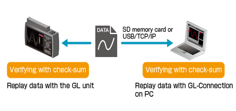
Data file verification
It is a function to check the integrity of the data file when replaying the data file. It compares check-sum generated from the data file and recorded check-sum. When two check-sums do not match, the data file may be corrupted or has been changed by someone. The check-sum code is recorded into the file when data file is created by the GL unit.
• Check-sum code is added to normal data recording file and also file created for backup, ring or relay recording. Adding check-sum is available for data files created in GBD format. When the recorded data file is converted and saved using GL100_240_840-APS or GL-Connection software, the check-sum code will not match.
• This function is available with firmware version 1.43 or rater.
Multiple PC Interfaces Depending on Measurement Environment
Connection to your PC can be made via USB, wireless LAN or wired LAN. *Optional B-568 is required for wireless LAN connection. The USB connection is a common A-B type cable.
Wireless connection with PC using Optional Wireless LAN unit (B-568)
*Optional Wireless LAN unit is available in limited region.
Wireless LAN option enables the wireless communication with the other devices.
Access Point enables direct connection to PCs and smart devices without a router. Station enables connection to a wireless LAN router. Depending on the environment, data can be checked and e-mails can be received with remote PCs and smart devices via the Internet.
Wired connection with PC by Ethernet (10BASE-T / 100BASE-TX)
One-to-one connection with a PC or multiple connections via a HUB are possible.
Modbus/TCP
Data recorded by GL860 can be transferred to PLC via Modbus communication. Recording start/stop control of GL860 is available from PLC. For more information on Modbus communication, please apply us for the SDK.
New service “G-REMOTE”*Additional charge for use.
Remote control and data capture can be easily performed using a web browser from anywhere with an Internet connection. The recorded data can be backed up to a dedicated cloud server.
Maximum 200ch available for 1 terminal(20ch/30ch) or extension unit
External input/ output※1
Input
Trigger or Sampling (1 channel), Logic/Pulse (4 channels) Voltage range :0 – +24V(common ground) Input signal: No-voltage contact (a-contact, b-contact, NO, NC), Open collector, Voltage input
Output
Alarm (4ch) Output signal: Open collector (pull-up to 5V by 10kΩ resistor)
Sampling interval
5ms – 1h(5ms – 50ms is available for voltage and humidity, Number of channels is limited, external ※1
TIME / DIV
1s~24h
Trigger function
Repeat action
Off・On
Trigger type
Start: Data capture starts when a trigger is generated. Stop: Data capture stops when a trigger is generated.
Trigger setting
(Start / Stop) Off, Level, Alarm, External, Time, Date, Week
Alarm function
Alarm judgment mode
Detection method: Level, Edge Analog channel judgment mode: H (↑), L (↓), Window In, Window Out Logic channel judgment mode: H (↑), L (↓) Pulse channel judgment mode: H (↑), L (↓), Window In, Window Out Calculation channel judgment mode: H (↑), L (↓), Window In, Window Out
Maximum input frequency : 50kHz Maximum number of count : 50kC/sampling (16-bit counter)
PC I/F
USB2.0 (Hi-speed), Ethernet (10BASE-T / 100BASE-TX), Wireless LAN(using B-568 option) * B-568 is available in limited region.
Storage device
Internal
Built-in 8GB Flash Memory *2
External *3
One SD card slot (Support SDHC memory card, up to 32GB)*2*3
Saved contents
Setup conditions Measured data Screen copy
Operating environment
0 to 45 ºC, 5 to 85 % RH (0 to 40°C when operated in batteries/15 to 35°C when a battery is charging)
Power supply
AC adapter
AC100~240V / 50~60Hz
DC input
DC8.5 – 24V (Max. 26.4V)
Battery pack *Optional item
DC7.2V (2875mAh) (*Two packs can be mounted)
Power consumption
36VA or lower (When using the AC adapter, the LCD is on, During recharging battery, AC100V)
Vibration- tested conditions
Equivalent to Equivalent to Automobile parts Type 1 Class A Buzzer
*1. Input/Output cable for GL (option B-513) is required. *2. Each recorded file is limited to 2GB. *3. When the wireless LAN (B-568, optional item) is installed, the SD memory card cannot be inserted into the SD CARD slot.
Real-time data (CSV, GBD Binary) Data in Internal memory or SD memory card (CSV, GBD binary)
Display
Analog waveforms, logic waveforms, pulse waveforms, digital values
Display modes
Y-T View, Digital View, X-Y View between Cursors (only during replay)
File conversion
Between cursors, All data
Monitor functions
Alarm monitor enables sending of email to the specified address
Statistic/History
Displays maximum, minimum and average values during measurement
Report function
Enables creation of daily or monthly files
Standard Accessories
スクロールできます
Item
Description
Notice
This document provides a clear explanation of the basic operations(Qty,1)
TO ENSURE SAFE AND CORRECT USE
This document contains important information to ensure the safe and proper use of the product (Qty,1)
AC adaptor
AC100 – 240V, 50/60Hz, Power supply cord for each area
Wireless LAN unit B-568 (option) specifications
スクロールできます
Item
Description
Model number
B-568 * Available in limited regions.
Communication method
Wireless communication
Installation
Mounted in SD CARD slot * When the wireless unit is inserted, the SD memory card cannot be inserted into the SD CARD slot.
Wireless LAN standard
IEEE802.11b / g / n
Function
Control from PC, data transfer to PC, control and data transfer from smartphone/tablet For access point: Local control and transfer are possible. For station: In addition to local, remote control and transfer using G-REMOTE is also possible. Communication range: Approx. 40 m Communication range depends on the obstacles and the surrounding environmental conditions. WPS: Push button method / PIN method Encryption function: WEP64, WEP128, WPA-PSK/WPA 2-PSK (TKIP/AES) WPA/WPA2 and TKIP/AES are automatically selected.
Humidity Sensor B-530 (option) Specifications
スクロールできます
Item
Description
Allowable temperature range
-25~80℃
Allowable humidity range
0~100% RH
Relative humidity measurement accuracy
±3% RH(5~98% RH at 25℃)
Method
Capacitance method
Relative humidity measurement accuracy (5 to 98%)
Measurement environment
Measurement accuracy
0~10℃
±5% RH
10~20℃
±4% RH
20~30℃
±3% RH
30~40℃
±4% RH
40~50℃
±5% RH
50~60℃
±6% RH
60~70℃
±7% RH
70~80℃
±8% RH
Measurement accuracy at 60°C or more is a reference value.
Response time
15 sec. (90% response when membrane filter is installed)
Sensor output
DCO~1V
External dimensions
φ14 × 80 mm (excluding cable)
Cable length
3m
Sensor power source
DC+5V~+16V
Power consumption
approx. 4 mA
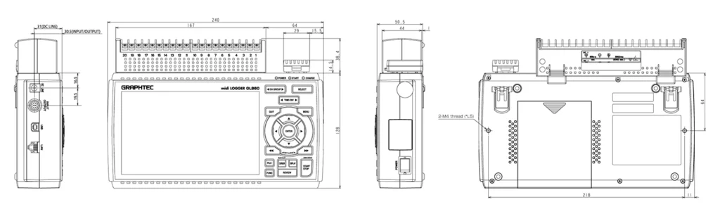
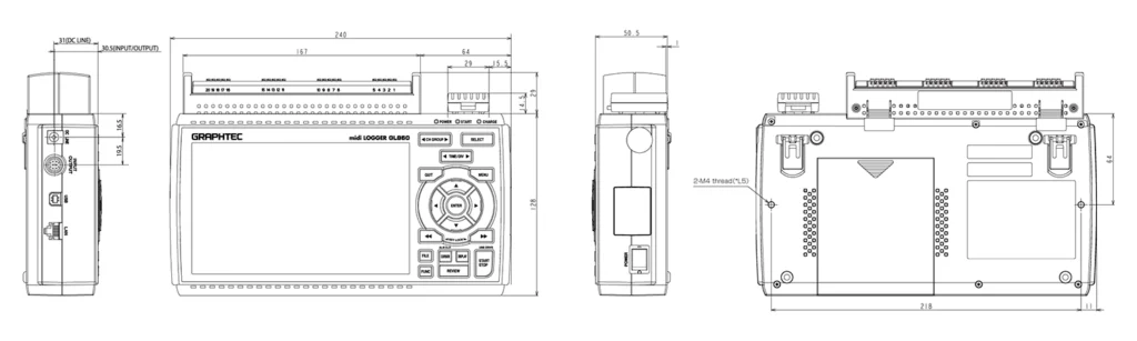
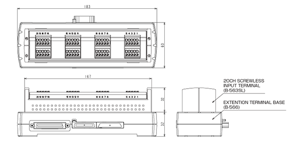
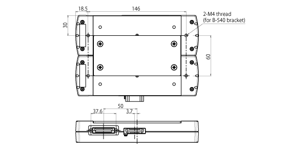
Dimensions
GL860 External Dimensions (When B-565 & B-568 are attached)
Scale: mm Tolerance: ±3mm
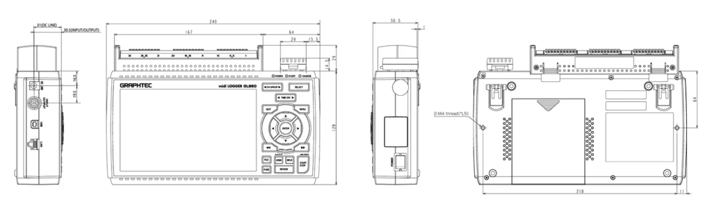
GL860 External Dimensions (When B-563SL-30 & B-568 are attached)
Scale: mm Tolerance: ±3mm
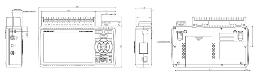
GL860 External Dimensions (When B-563 & B-568 are attached)
Scale: mm Tolerance: ±3mm
GL860 External Dimensions (When B-563SL & B-568)
Scale: mm Tolerance: ±3mm
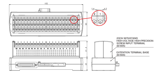
WITHSTAND HIGH-VOLTAGE HIGH-PRECISION TERMINAL (B-565) / Extension Terminal Base (B-566)
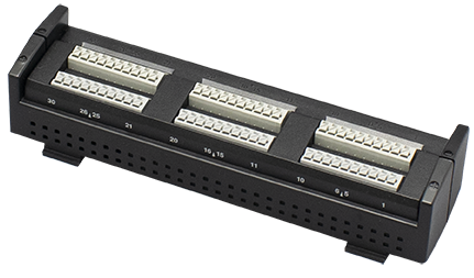
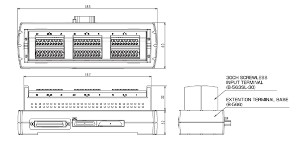
30CH SCREW LESS INPUT TERMINAL (B-563SL-30) / Extension Terminal Base (B-566)
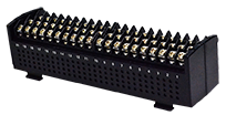
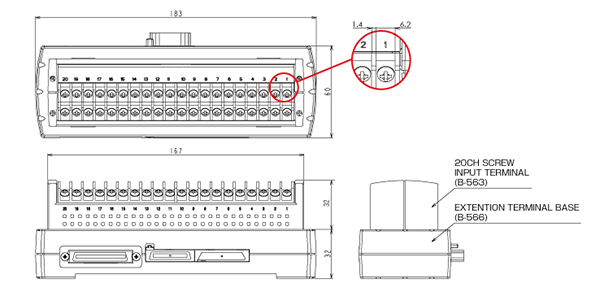
20CH INPUT TERMINAL (B-563) / Extension Terminal Base (B-566)
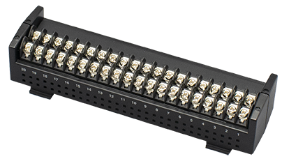
20CH SCREW LESS INPUT TERMINAL (B-563SL) / Extension Terminal Base (B-566)
Extension Terminal Base (B-566)
Scale: mm Tolerance: ±3mm
When connecting two Extension Terminal Bases (B-566)
Scale: mm Tolerance: ±3mm
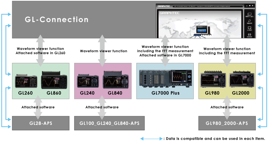
Software for high performance and easy operation Allows connections of Graphtec’s midiLOGGER series
The GL-Connection software included with GL7000, GL2000, GL980,GL860 and GL260 can control devices. It is an integrated application software for the GL series, the GL900, GL860, GL840, GL820, GL260, GL240 and GL220 can also be connected and controll
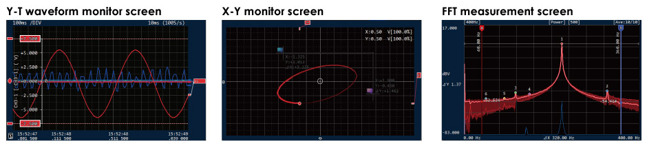
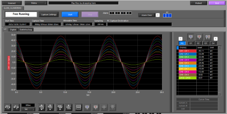
The measurement signal can be displayed in various types of screens adapted to applications.
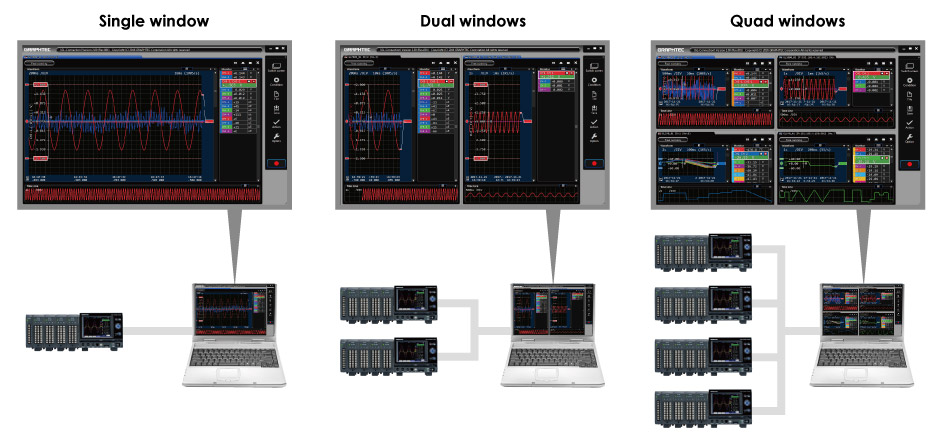
Multi-window function, measured signal can be displayed in various forms
Multi-window function
The GL-Connection software supports up to 2000 channels and up to 20 units of the GL series. It splits up to 4 windows and each window can display different format for easy monitoring signal in large channels.
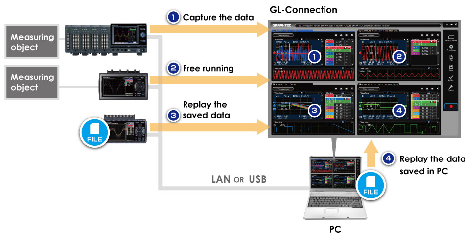
When the unit of GL series is connected to the PC via Ethernet or USB, the GL-Connection software can manage a various information such as the data in capturing, data in the free running – displaying data without saving – and data in saved file. The GL-Connection software can also display the data saved on the PC.
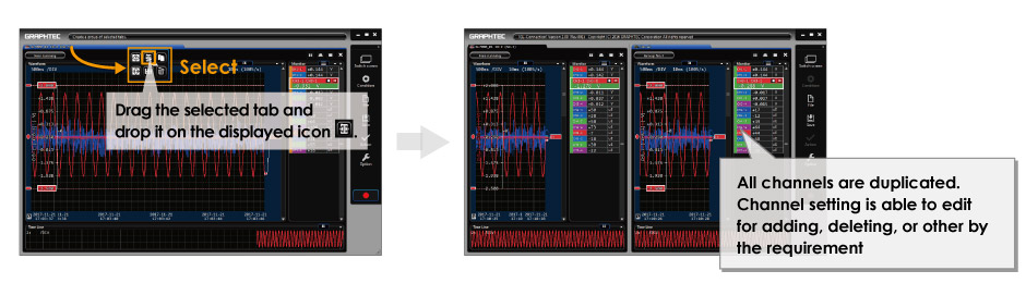
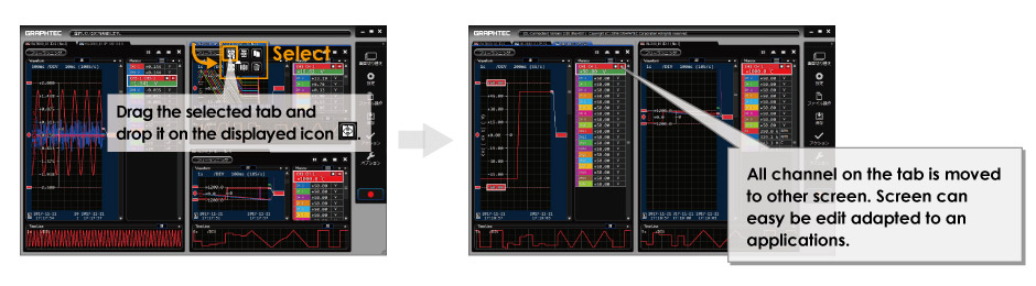
Tab function
The tab function allows you to manage the screen so that it can be intuitive and easy monitoring. Screen displayed in multi-window can split using the tab and selected items can be displayed. Items to be displayed can be set in detail, such as the GL body level, individual input module level, the specified channel, and other settings.
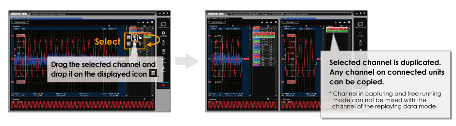
Copy of the entire tab
Copy of the channel
Move of the tab
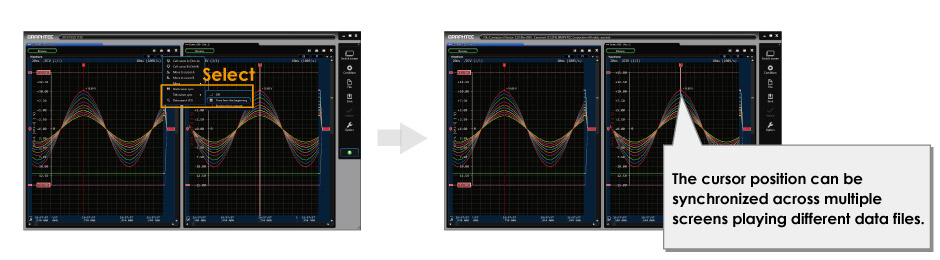
Cursor synchronization
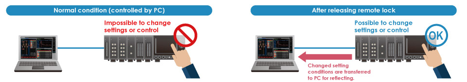
Release of remote lock of GL7000
Integrated application software for the GL series
When the software is used with the GL7000, it can be controlled and displayed the data including the FFT measurement. When other GL series is used, the software has mainly the waveform viewing function and have also the function to control basic items. Data captured by other GL series is compatible with the GL-Connection and APS software.
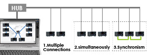
Connection of multiple units and the integrating function of the saved data
GL-connection software will be able to manage multiple units in a mixed condition of the GL series. Data integration function allows you to understand the overall situation immediately by creating single file at the same time axis from multiple data file saved by each unit.
スクロールできます
Connection method
Model
Modelmixed
Control of Start/Stop
Data integration
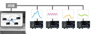
1.Multiple unit connection
GL7000 Plus GL2000 GL980 GL860 GL840 GL260 GL240 GLT400
Yes
It make operation for each unit.
It makes manually after completing the data capture.
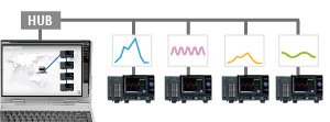
2.Link connection (simultaneous)
GL7000 Plus GL2000 GL980 GL860 GL840 GL260 GL240 GLT400
Yes
All units make the action in a single operation. * The timing of the action is maybe synchronized.
It makes automatically after completing the data capture. It can also make manually.
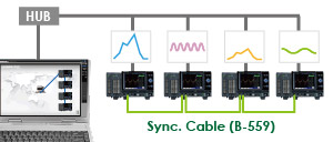
3.Link connection (synchronous) * Sync cable is used to connect each unit.
GL7000 Plus
No
All units make the action with full synchronization in a single operation.
It makes automatically after completing the data capture. It can also make manually.
4.Mixed connection, mixing of No.1 to No.3
GL7000 Plus GL2000 GL980 GL860 GL840 GL260 GL240 GLT400
Way of operation or action vary by type of connection that is the No.1 to No.3. * Full synchronization can be made when the sync cable is used in the GL7000.
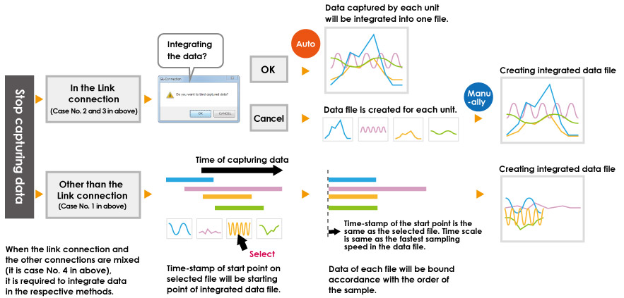
データ結合の流れ
The integrated file cannot be created when it exceeds 100 units or 100 channels (analog channel + logic channel).
Data will be integrated with using fastest sampling speed when the sampling speed in each file is different.
The data format in integrated data file is the GL7000 format even if GL series is included to capture the data.
Main function of software
スクロールできます
Item
Description
GL-Connection (version 2.0 or later) *GL260 (v.2.60 or later) *GL860 (v.2.70 or later) *GLT400 (v.2.50 or later)
Connection
Supported model
GL7000, GL2000, GL980 GL900-4/-8 (Firm. v. 3.01 or later) GL860 GL840 (Firm. v. 1.21 or later) GL820 (Firm. v. 1.08 or later) GL260 GLT400 GL240 (Firm. v. 1.21 or later) GL220 (Firm. v. 1.06 or later)
Max. number of unit
20
Max. number of channel
2000
Mixing the USB & LAN
Possible
Display
Splitting of screen
Up to 4 screens
Group function
Up to 20 groups
GL980_2000-APS
Connection
Supported model
GL2000 / GL980
Max. number of unit
1
Max. number of channel
4 or 8
Mixing the USB & LAN
N/A
Display
Splitting of screen
No, single screen
Group function
N/A
GL100_GL240_GL840-APS
Connection
Supported model
GL840 / GL240 / GL820 / GL220 / GL100
Max. number of unit
10
Max. number of channel
1000
Mixing the USB & LAN
Possible
Display
Splitting of screen
No, single screen
Group function
Up to 4 groups
GL28-APS
Connection
Supported model
GL860 / GL840 / GL260 / GL240
Max. number of unit
10
Max. number of channel
1000
Mixing the USB & LAN
Possible
Display
Splitting of screen
No, single screen
Group function
Up to 4 groups
GL220_820-APS
Connection
Supported model
GL820 / GL800 / GL220 / GL200A
Max. number of unit
10
Max. number of channel
500
Mixing the USB & LAN
N/A
Display
Splitting of screen
No, single screen
Group function
Up to 4 groups
GL900-APS
Connection
Supported model
GL900-4 / GL900-8
Max. number of unit
1
Max. number of channel
4 or 8
Mixing the USB & LAN
N/A
Display
Splitting of screen
No, single screen
Group function
N/A
Supported model and condition of connection
スクロールできます
Supported model
Connected by USB
Connected by LAN
Wireless LANN
Notice
GL7000
Yes
Yes
N/A
(1) GL series up to 20 units (2) Up to 2000 channels
GL2000 / GL980
Yes
Yes
N/A
GL860
Yes
Yes
Yes ※
GL840
Yes
Yes
Yes ※
GL260
Yes
N/A
Yes ※
GL240
Yes
N/A
Yes ※
GLT400
Yes
Yes
Yes ※
GL900
Yes
Yes
N/A
GL820
Yes
Yes
N/A
GL220
Yes
N/A
N/A
using B-568 option.
B-568 is available in limited region.
Sampling Limits
High speed sampling is limited by the number of recording channels, connected modules, and the recording destination, etc. Even within the following limits, transmission may be incomplete due to transmission delays with multiple module connections, especially with LAN connections. If this occurs, please reduce the sampling rate. For more details on the GL device limits, please refer to the main module user’s manual on CD-ROM.
100 ms * The GL device’s calculation function cannot be used with this application. There is no calculation function in this application.
Ring recording-based limit. (GL device limits)
Ring recording-based limit. (GL device main module limits) When ring recording is on:100ms (Only when Internal Flash, SD card, SSD module)
Transmission-based limits (Application limits)
There are estimated sampling settings for PC recording depending on the volume of data communication. * When connecting through an existing network such as a LAN connection, communication may not be possible within the following limits. In such a case, please use a USB connection, or set a lower sampling rate. Estimated sampling rates
USB connection
GBD (binary) format
1ms/5Unit
CSV (text) format
1ms/5Unit
LAN connection
GBD (binary) format
1ms/5Unit
CSV (text) format
1ms/5Unit
GL860、GL840、GL260、GL240、GLT400、GL820、GL220
スクロールできます
Name
Explanation
Limitations by amplifier (Limitations of the GL module side)
Number of CH available
Fastest sampling
1
10ms
2
20ms
3~5
50ms
6~10
100ms
11~20
200ms
21~50
500ms
51~100
1s
101~200
2s
* The number of channels of the GS/WL sensors is not included
Main module recording format-based limits (GL device limits)
Main module recording format-based limits (GL device limits)
GBD (binary)
1ms~
CSV (Text)
10ms~
Functions
スクロールできます
Item
Description
Module Settings List
Settings of multiple modules can be displayed simultaneously, and setting conditions can now be saved as CSV data.
Remote Lock On/Off Feature
Setting operation is available on GL7000 under control of GL-Connection.
Statistics / Display
Display statistical calculation result. Capturing data: Maximum, Minimum, Peak or Average Replaying data: Maximum, Minimum, Peak, Average or RMS in between cursors
Check-sum function
It is a function to check data file consistency. The check-sum code is recorded into the file when data file is created by the GL unit. When the content of the file is changed by someone, the check-sum generated from the file does not match with the recorded check-sum, which indicates that the file has been tampered with. * This software and the firmware on the GL unit need to be a version that supporting the check-sum function.
File operation
Converts binary data to the CSV data (specific period, all data in one file, multiple files), Creates a new file with compression or by consolidating multiple files.
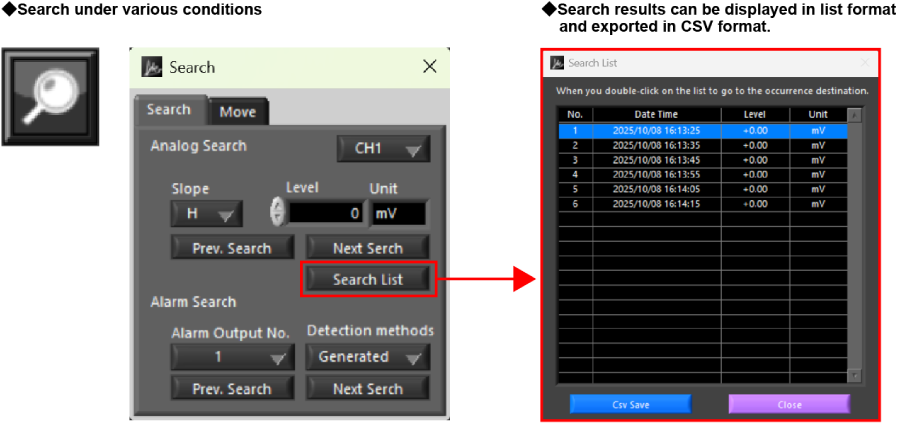
Search function
Search any point on the data. Level: Specific level in any channels Alarm: Occurred alarm in any channel Time: Beginning, center, end of the data, Trigger point, Specific time (absolute, relative), Specific number
Warning function
Send e-mail to the specified address when the alarms occur
Application Software for PC “GL28-APS”
Application Software for PC “GL28-APS”
The application software connects GL series to PC. It performs setting, recording, and managing the recorded data. It can connect and control up to 10 units of GL series or 1000ch.
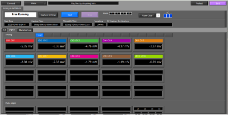
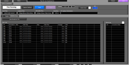
3 types of measurement screens: Y-T view, digital view, and statistics and history display. Direct Excel Function enables users to send data directly to Excel at the start of measurement.
◆ Y-T View
◆ Digital View
◆ Statistics and History Display
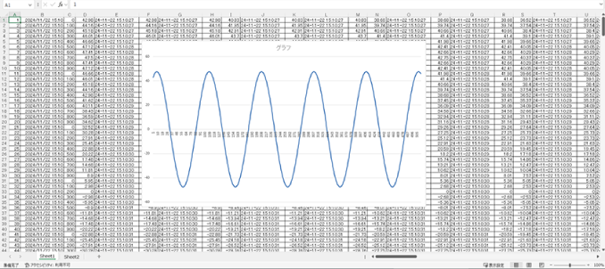
◆ Direct Excel Function
.
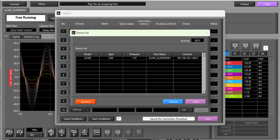
Connected Device Search Function
Devices can be automatically detected without requiring detailed connection settings.
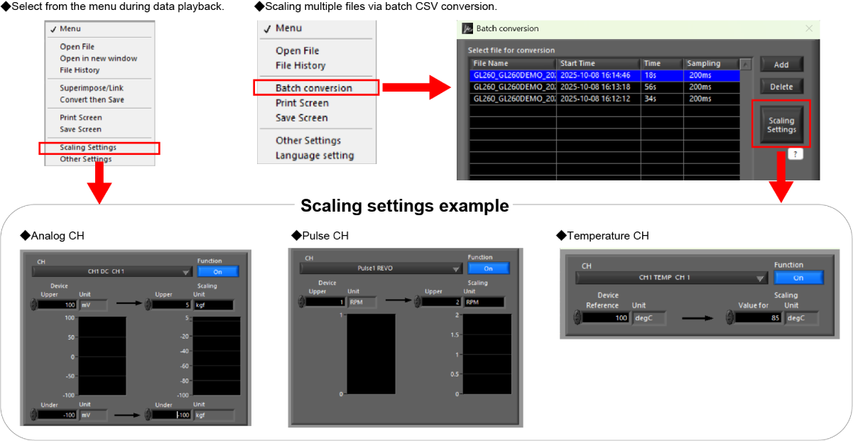
Offline Scaling of Measurement Data
Scaling settings can be modified offline for recorded GBD data files. During GBD data playback, scaling settings can be adjusted via “Menu” > “Scaling Settings.” After changing the scaling settings, the updated values will be saved by selecting “Convert then Save.” Scaling settings can also be applied to multiple files using the “CSV File Batch Conversion” feature. Settings are applied to the first selected file in the list, and scaling is applied to subsequent files only if they share the same conditions as the first file. The conditions are as follows:
The number of channels, inputs, and ranges of the analog channels (including GS sensors) are identical
The number of channels, and inputs of the pulse channels (including GS sensors) are identical
The existing scaling settings are identical
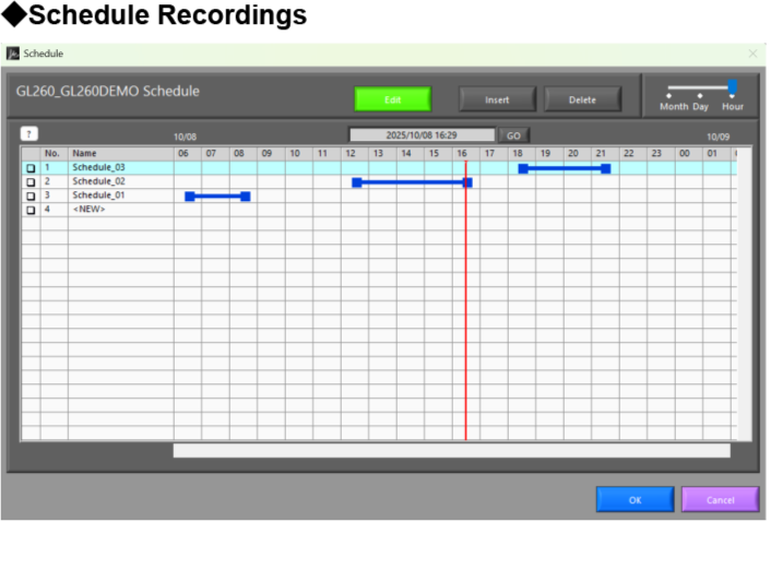
Scheduling Function
Measurement start / stop can be scheduled in advance, allowing automatic start and stop without manual operation.
List Display of Search Results
By setting search conditions, results are displayed in a list and can be exported as a CSV file.
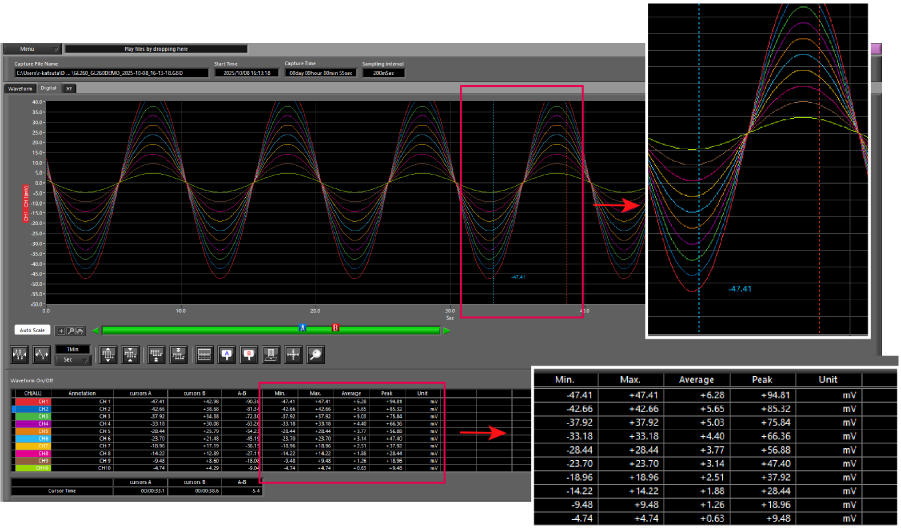
Custom Range Statistics Display
Displays statistical calculation results—maximum, minimum, average, and peak-to-peak—for any selected range.
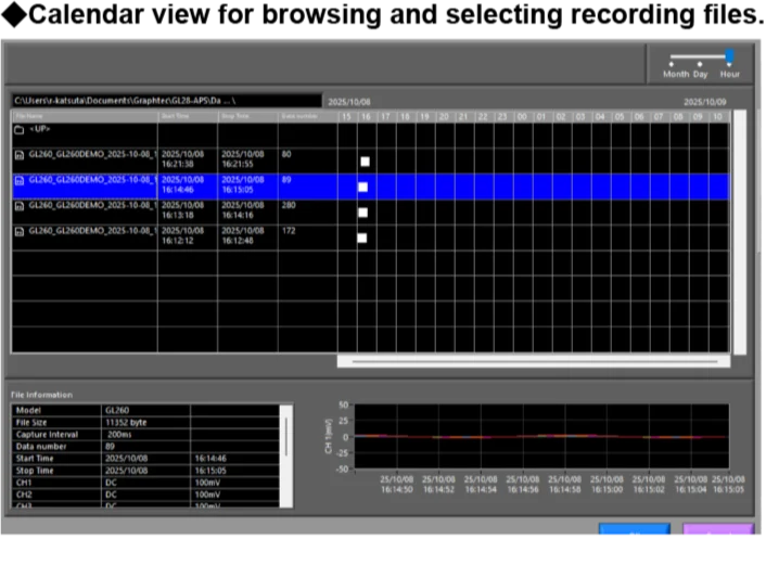
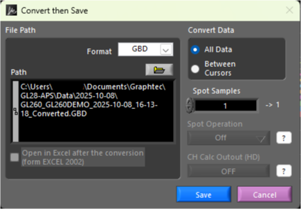
Save and Convert Playback Data
Playback data can be saved either as “All Data” or “Between Cursors”. The saved data can also be converted and saved in CSV format.
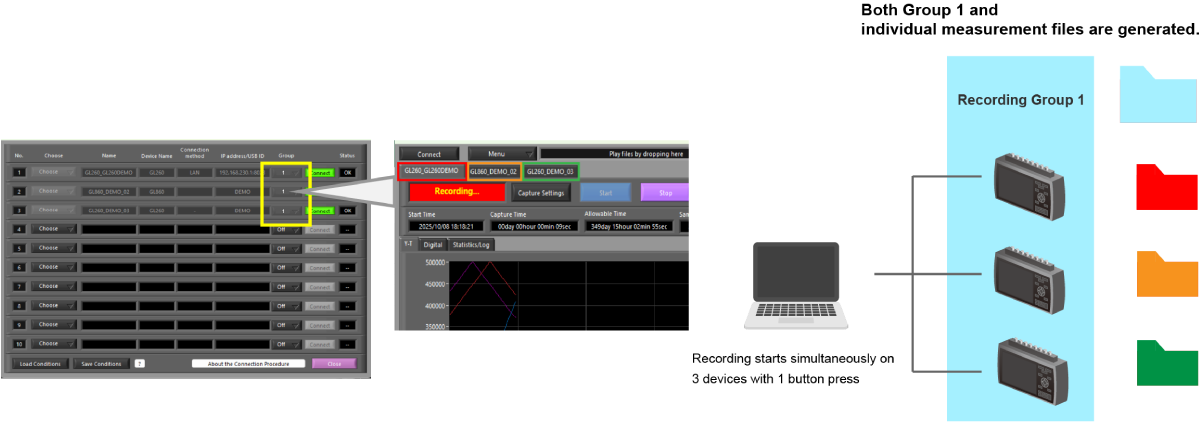
Synchronized Recording Across Multiple Devices and Automatic File Merging
Up to 4 recording groups can be created, with synchronized start and stop operations available for each group. When recording groups are set to the same group, measurement results can be saved not only as individual files but also as a single combined file.
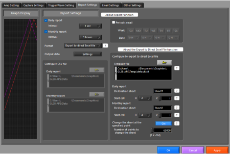
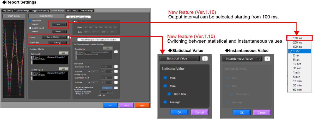
Export to Direct Excel File
During recording, data is transferred to Excel in real time, enabling the creation of daily and monthly reports using statistical values or instantaneous data.
Useful Features
Report Settings (Daily / Monthly)
Save and Load Settings
Screen Printing / Image Saving
Alarm Email Notification
Statistics and Alarm History Display
Data Overwrite and Merge
Features Available Only When GL240 or GL840 Is Connected *Same functions as GL100/240/840-APS
To provide the best experiences, we use technologies like cookies to store and/or access device information. Consenting to these technologies will allow us to process data such as browsing behavior or unique IDs on this site. Not consenting or withdrawing consent, may adversely affect certain features and functions.
Functional
Always active
The technical storage or access is strictly necessary for the legitimate purpose of enabling the use of a specific service explicitly requested by the subscriber or user, or for the sole purpose of carrying out the transmission of a communication over an electronic communications network.
Preferences
The technical storage or access is necessary for the legitimate purpose of storing preferences that are not requested by the subscriber or user.
Statistics
The technical storage or access that is used exclusively for statistical purposes.The technical storage or access that is used exclusively for anonymous statistical purposes. Without a subpoena, voluntary compliance on the part of your Internet Service Provider, or additional records from a third party, information stored or retrieved for this purpose alone cannot usually be used to identify you.
Marketing
The technical storage or access is required to create user profiles to send advertising, or to track the user on a website or across several websites for similar marketing purposes.